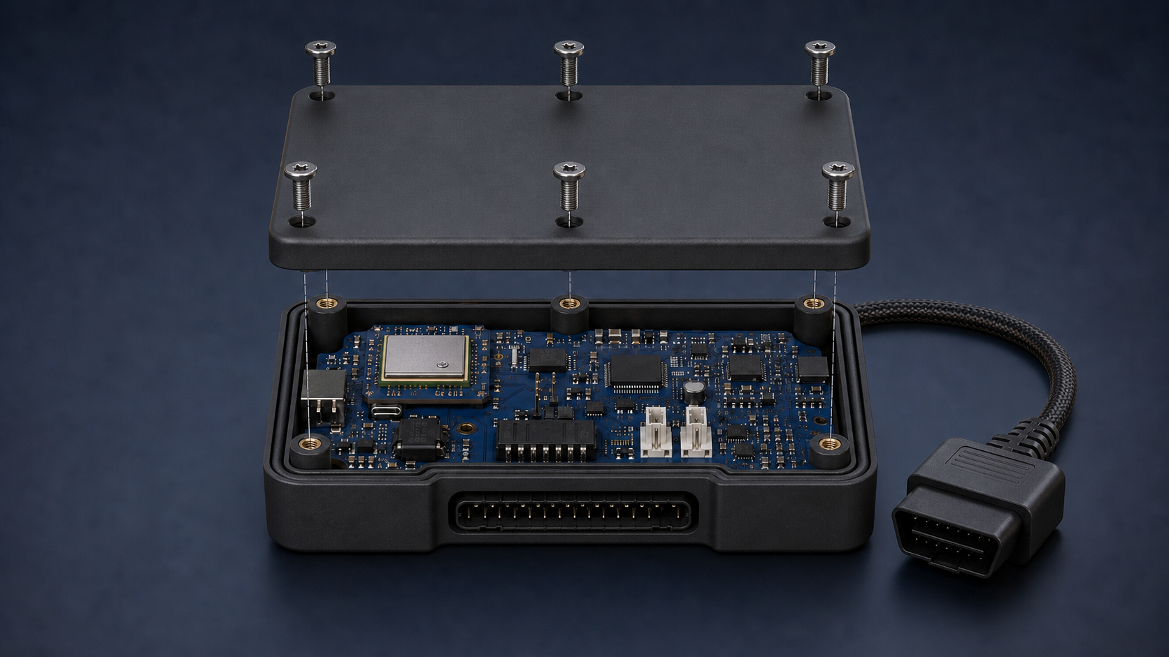
Six matched positions
Three fasteners along each long side reduce the chance of the middle lifting.
Fleet-monitoring device • researched reference design v3
Rotate the model freely, open the enclosure and point at each scaled package to connect it with a real manufacturer, order code, interface and evidence source.
Interactive reference design
Scaled package bodies—simplified pins and pads
Connection path
The USB-C service port follows a separate path to an authorised technician. Diagnostic read requests may transmit a limited query, but the product boundary excludes steering, braking, acceleration, airbag and engine-control commands.
Why the casing changed
The earlier image did not make every screw-to-post relationship clear. This revision uses one shared pattern for the lid recesses, screw shafts and metal inserts, so every pair is centred on the same axis.
Three fasteners along each long side reduce the chance of the middle lifting.
The seal sits inside the screw line and is not crossed by cables or mounting holes.
Captive M3 screws enter metal inserts instead of repeatedly cutting into plastic.
Heat is handled internally so dust and moisture are not invited into the electronics.
Important boundary
Diagnostic reading can require a limited query to the vehicle, so “monitoring only” must be enforced by a validated approved-command list and a controlled transmit path—not by pretending the CAN link can never transmit. The design must not command steering, braking, acceleration or airbags, and must never stop a moving engine. Sealing, heat, vibration, EMC, electrical transients and radio approval all require independent testing.